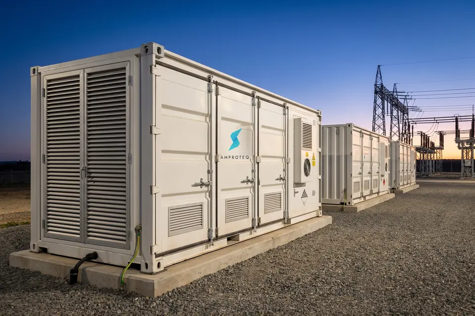
A625Flagship
6.25 MWh
The largest block we build. The replication unit for utility and IPP plants where land, civils and cable routes are the binding constraint.
6.25MWhEnergy
3.13MWAt 0.5C
2–6hDuration
 AMPROTEQ
A 314 Ah lithium iron phosphate prismatic cell — the safest large-format chemistry in commercial service. Serialised, traceable, tested before it leaves the line.
Cells are welded into a series string and clamped in an aluminium housing, with a liquid-cooling cold plate beneath them and cell-level voltage and temperature sensing on top.
Packs stack into a rack and connect in series through a cluster controller with its own contactors, fusing and pre-charge. Each cluster is an independently managed DC source.
A standard 10 ft high-cube. Four clusters on a shared coolant manifold, four bidirectional PCS modules, the isolation transformer and the Solaris™ controller, with the liquid-cooling unit behind the louvered end door. Assembled and burned in at the factory.
Site scope is a plinth, cable trenches, earthing and commissioning. Nothing arrives on your slab as a kit of parts. Separations and clearances follow the installation manual and NFPA 855 guidance.
The block’s 400 V output lands on a factory-tested skid carrying the step-up transformer, ring main unit, protection relays and metering. One skid serves several blocks.
The point of connection is the utility’s; the interface is ours — grid-code studies, reactive capability, ride-through and the connection application, built to NRS 097-2-1.
Half a megawatt in either direction, dispatched every four seconds by Solaris against the tariff calendar, the notified maximum demand and the reserve you hold for the day the grid goes away.
The same chain as the story above, hardware by hardware: 1 040 prismatic cells in twenty liquid-cooled packs, five packs to a cluster, four clusters to the block, with the cooling unit and power conversion in the same container.
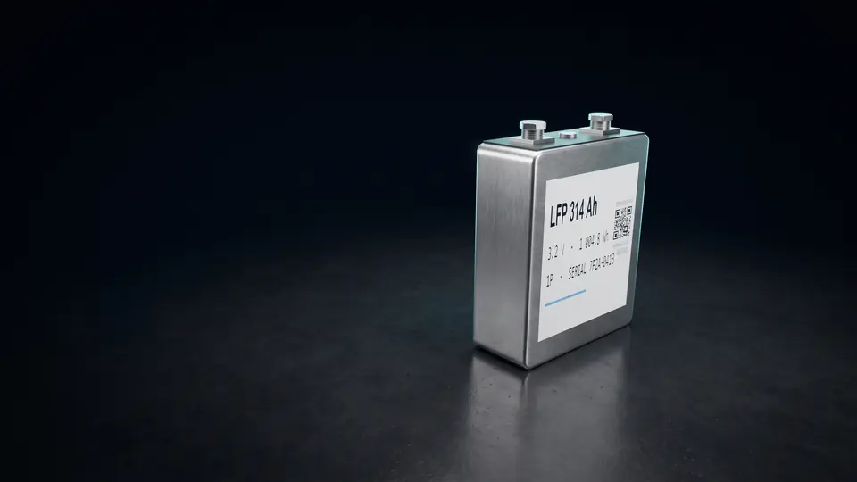
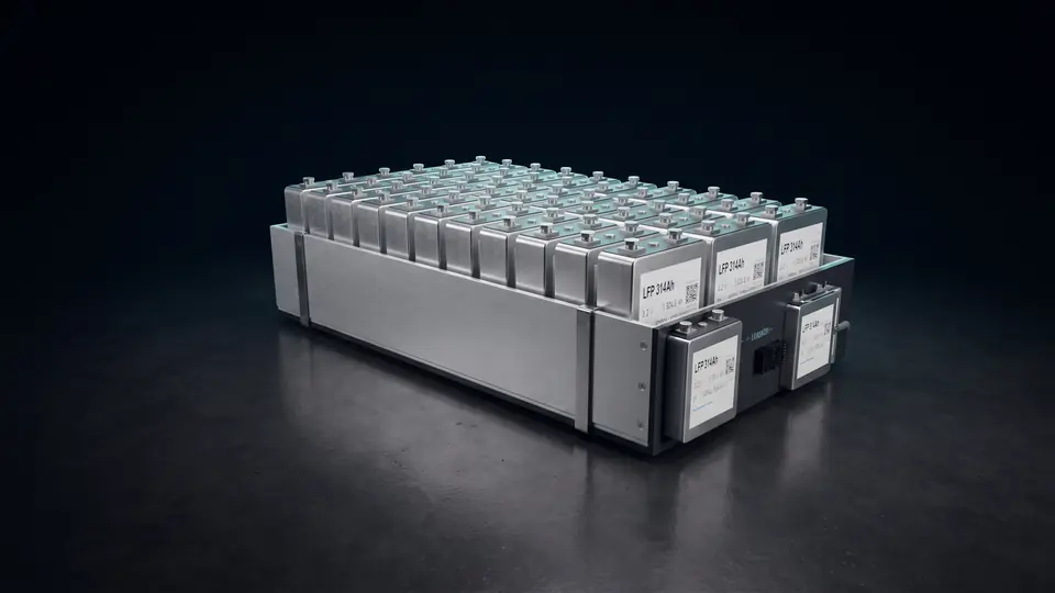
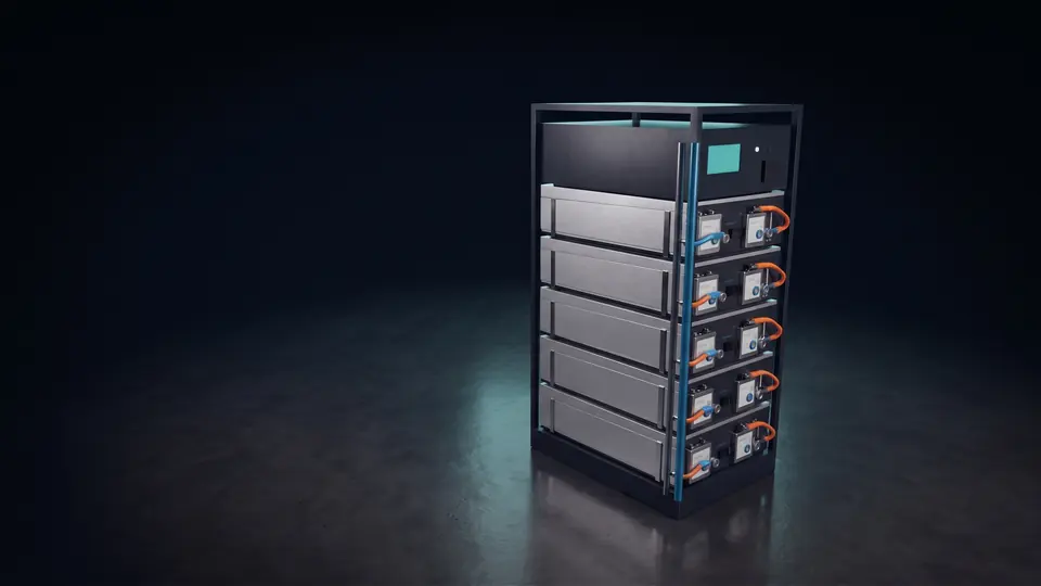
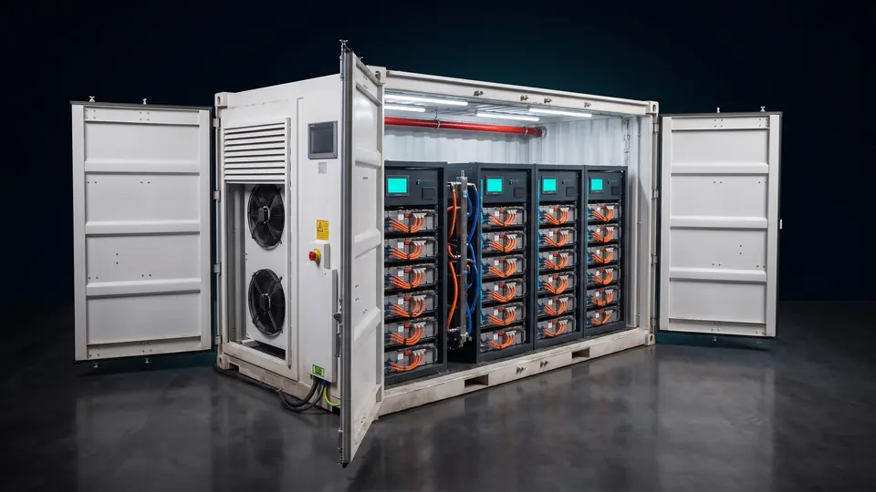
Visualisations of the A100 build
The 1 MWh block ships in a 10 ft container; the five larger blocks are 20 ft high-cubes. All are factory-integrated — battery racks, power conversion, liquid cooling, fire detection and suppression, switchgear and controls, assembled and burned in before dispatch. Every system runs at 0.5C or lower, so the cells are never worked hard.
The largest block we build. The replication unit for utility and IPP plants where land, civils and cable routes are the binding constraint.
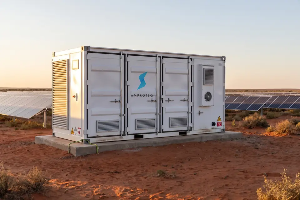
Utility-scale density in a standard footprint. Pairs cleanly with a 2.5 MW conversion stage and a single medium-voltage connection.

Sized for a large industrial site carrying both tariff peaks on stored energy, with headroom for load growth.

The most commonly specified block for commercial and mid-industrial sites paired with a 1 MWp-class solar array.
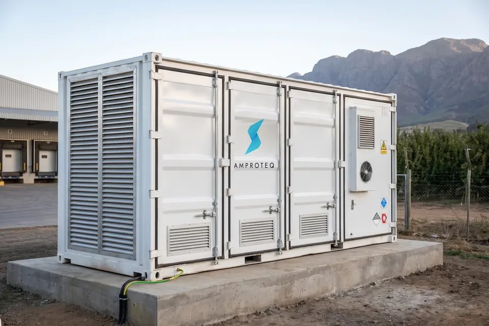
Two megawatt-hours in a 20 ft high-cube with room to spare — the block for a mid-industrial site that needs both tariff peaks carried on stored energy without a second unit.

The entry block, in a 10 ft container: 1 044 kWh of liquid-cooled LFP and an integrated 500 kW PCS at 400 V. One slab, one connection, one unit — and the same cells and controller as every system above it.
All six systems use the same cells, the same liquid-cooling circuit and the same controller. What changes between them is how much energy is in the container and how fast you take it out: the identical block is offered at 2, 4 or 6 hour duration (0.5C, 0.25C and 0.167C). Longer durations work the cells less hard and extend cycle life. Systems parallel to whatever the connection allows — a plant is counted in blocks, and the A100 adds them in 1 MWh steps.
Cell life is governed by temperature, and by how evenly that temperature is spread. Our integrated liquid-cooling system runs a cold plate through every module layer and holds deviation to 3 °C — against the 12–18 °C typical of forced-air compartments. Toggle the cooling mode and watch the pack.
This is the actual coolant circuit inside our containers. A supply header and a return header run the length of the rack line, with an individually valved branch to every single module position — not a shared plenum, not a compartment full of moving air.
That topology is why the pack holds 3 °C. Every module sees coolant at the same temperature, at the same flow rate, regardless of where it sits in the string. Redundant pumps and frequency-converted drives track the thermal load rather than running flat out, so auxiliary consumption stays low.
A pack ages at the rate of its worst cell, not its average. Compressing the spread from 15 °C to 3 °C is what turns a warranty schedule into something a lender will underwrite.
Coolant enters at 18 °C, passes through a serpentine channel in direct contact with every module, and returns at 23 °C. Frequency-converted pumps track load rather than running flat out.
Against an air-cooled equivalent in the same ambient conditions — and materially lower auxiliary consumption, because you are not conditioning a whole compartment of air.
We carry a full range of power conversion, matched to the system it serves. Modular strings scale in 100 kW steps, so the conversion stage is sized to the duty rather than rounded up to the nearest catalogue item.
| System | Energy | Converter at 2 h | Configuration | Grid interface |
|---|---|---|---|---|
| A625 | 6.25 MWh | 3 125 kW | Modular string PCS | 11 / 22 / 33 kV via MV skid |
| A500 | 5.00 MWh | 2 500 kW | Modular string PCS | 11 / 22 / 33 kV via MV skid |
| A400 | 4.00 MWh | 2 000 kW | Modular string PCS | 11 / 22 kV via MV skid |
| A300 | 3.00 MWh | 1 500 kW | Modular / integrated | 400 V or MV |
| A200 | 2.00 MWh | 1 000 kW | Modular / integrated | 400 V or MV |
| A100 | 1.00 MWh | 500 kW | Integrated PCS | 400 V 3P4W |
Hot-swappable conversion modules stack to the rating you need. A module fault costs one block of capacity and minutes of technician time — not a crane and a shutdown.
Full P/Q control across the capability curve, power factor adjustable −1 to +1, THDi below 3% at rated power. Reactive support available even when the battery is idle.
Grid-forming firmware provides synthetic inertia and voltage support on weak networks, with sub-10 ms transfer to island mode and battery-led black start where required.
Hot-swappable conversion modules stacking to megawatt-class stations. Four-quadrant P/Q control across the capability curve, power factor adjustable −1 to +1, THDi below 3% at rated power.
Step-up transformer, ring main unit and protection relays on a single factory-tested skid at 11, 22 or 33 kV. Built and tested as one unit, so site work is placement and terminations.
Integrated static transfer switch for sites that must ride through a network event. Sub-10 ms transfer to island mode, with battery-led black start where the site has no other source.
We build on one chemistry and we build on it properly. LFP is the safest lithium chemistry in commercial production, the most mature supply chain in the world, and with liquid cooling it delivers the cycle life a twenty-year commercial model needs.
The phosphate cathode is chemically stable at temperatures where other lithium chemistries begin to break down. Higher thermal runaway threshold, no oxygen release, and a far more benign failure mode — which is what your insurer and your fire engineer will ask about first.
To 70% state of health at one full cycle a day and 98% depth of discharge — nineteen years of daily cycling; over 10 000 at 80% depth. Measured, not modelled: the retention lab below is the cell manufacturer’s own tabulated test set, and because we hold the pack within 3 °C the cells actually reach it.
Iron and phosphate rather than scarce, price-volatile metals. That means a cost curve that keeps falling, a supply chain that is not a single point of failure, and a materially cleaner sourcing story for your ESG reporting.
The cell manufacturer’s tabulated 20-year test set, transcribed without adjustment: state of health year by year across ten dispatch duties at 98% depth of discharge, plus 90% and 80% depth at three duties. Not an illustrative shape with a specified end point. Storage is sized with the end of the term in mind, and augmentation is priced into the model from the start.
| System | Energy | Power at 2 h | Chemistry | Cooling | Typical application |
|---|---|---|---|---|---|
| A100 · 10 ft | 1.00 MWh | 500 kW | LFP | Liquid | Commercial / entry industrial · adds in 1 MWh steps |
| A200 | 2.00 MWh | 1 000 kW | LFP | Liquid | Commercial / mid-industrial with solar |
| A300 | 3.00 MWh | 1 500 kW | LFP | Liquid | Mid-industrial with solar |
| A400 | 4.00 MWh | 2 000 kW | LFP | Liquid | Large industrial site |
| A500 | 5.00 MWh | 2 500 kW | LFP | Liquid | Utility / IPP node |
| A625 | 6.25 MWh | 3 125 kW | LFP | Liquid | Utility replication unit |
Duration is a commissioning choice, not a different product. The container, the cells and the cooling are identical — only the conversion rating and the dispatch envelope change.
| System | Energy | 2 h · 0.5C | 4 h · 0.25C | 6 h · 0.167C |
|---|---|---|---|---|
| A100 | 1.00 MWh | 500 kW | 250 kW | 167 kW |
| A200 | 2.00 MWh | 1 000 kW | 500 kW | 333 kW |
| A300 | 3.00 MWh | 1 500 kW | 750 kW | 500 kW |
| A400 | 4.00 MWh | 2 000 kW | 1 000 kW | 667 kW |
| A500 | 5.00 MWh | 2 500 kW | 1 250 kW | 833 kW |
| A625 | 6.25 MWh | 3 125 kW | 1 563 kW | 1 042 kW |
The systems differ in capacity, not in design. Chemistry, DC architecture, protection, cooling, controls and compliance are identical across the range, which is what makes a site upgrade a question of adding blocks rather than requalifying a platform.
| Battery & DC architecture | |
|---|---|
| Cell chemistry | LFP — LiFePO₄, prismatic |
| Cell nominal voltage | 3.2 V |
| System DC voltage | 1 500 V DC maximum · A100: 936 V |
| DC operating window | 1 120 – 1 500 V · A100: 728 – 936 V |
| Usable depth of discharge | 90% |
| Continuous C-rate | 0.5C / 0.25C / 0.167C |
| Duration options | 2 h / 4 h / 6 h |
| Round-trip efficiency | ≥ 88% AC–AC system · 94.0% DC battery, beginning of life |
| Cycle life to 70% SOH | ≈ 7 000 at 1 cycle/day, 98% DOD · > 10 000 at 80% DOD (measured) |
| Battery management | Three-level — cell, rack, system |
| Enclosure, environment & safety | |
|---|---|
| Enclosure | A100: 10 ft ISO container · A200–A625: 20 ft high-cube |
| External dimensions | 2 991 (A100) or 6 058 × 2 438 × 2 896 mm |
| Ingress protection | IP55 · A100: IP54 |
| Corrosion class | C5 (ISO 12944-2) |
| Cooling | Closed-loop liquid, glycol |
| Cell temperature deviation | ≤ 3 °C across pack |
| Operating temperature | 20 ft: −30 … +55 °C · A100: −25 … +60 °C |
| Relative humidity | 5 – 95%, non-condensing |
| Altitude | ≤ 2 000 m without derating |
| Fire detection & suppression | Aspirating smoke, gas detection, aerosol |
| Conversion & grid | |
|---|---|
| Grid modes | On-grid / off-grid / hybrid |
| Transfer time (STS) | < 10 ms |
| Power factor | −1 to +1, four-quadrant |
| Current distortion | THDi < 3% at rated power |
| MV output | 11 / 22 / 33 kV via MV skid |
| LV output | 400 V 3P4W |
| Controls & compliance | |
|---|---|
| Energy management | Solaris™ |
| Protocols | Modbus TCP/RTU, IEC 60870-5-104, IEC 61850 |
| Remote access | Encrypted VPN, on-site HMI |
| Cell & system standards | IEC 62619, IEC 62477, UN38.3, CE · holders |
| EMC | IEC 61000 |
| Grid code | NRS 097-2-1, SA RPP capable |